Tin Chiang
Background
In the Contact Force Estimation Project on Raven-II, we modified the original control software of Raven-II on RT Linux to manage the torque of DC motors. The complex multi-layer system architecture makes motor control challenging, and implementing the feedback controller on ROS introduces delays due to its asynchronous nature. Additionally, the hardware of the Raven-II remains somewhat opaque to me, and I'm eager to gain a deeper understanding of its inner workings.
Brief Intro
The project aims to understand the hardware architecture of the Raven-II Surgical Robot System and develop a prototype that can serve as the controller for the force control system. We delved into Raven-II's hardware at the PCB level to gain direct control of the DC motors By redesigning the control board. This effort not only improved the controller's response but also offloaded some computational tasks from the Raven-II's control desktop.
Contribution
-
Rebuilt and tested a servo driver system of Raven-II using discarded parts in the lab.
-
Redesigned the schematics of the motor control board:
-
Reorganized the peripheral to enable individual control of each motor.
-
Upgraded the microcontroller from 8-bit to 32-bit.
-
-
Assisted in the PCB production process.
Skills
-
PCB Design(KiCAD)
-
PCB Debugging
-
Schematic Reading
-
I2C, SPI Communication
-
DC Motor Control
-
Soldering


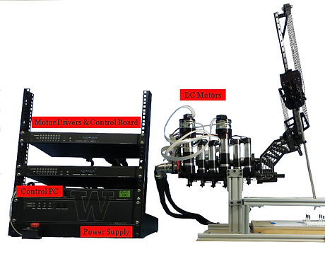
Hardware Components of Raven-II's Servo System
The Raven-II system features high-quality current-control electronics and DC motors, making it ideal for force control applications. The electronics are divided into three main components:
-
Power Box: Contains dual power supplies and a PLC for safety functions.
-
Control Box: Houses motor drivers and a USB board that handles motor control and feedback signals to the control PC.
-
Control PC: An RT Linux machine that runs Raven-II's control software and the ROS API for research purposes.

Rebuilt a Servo System
The Raven-II Surgical Robot lacks comprehensive hardware documentation, necessitating reverse engineering to gain a deeper understanding.
To avoid damaging operational units, I gathered discarded components from the lab and assembled a minimal servo system as a test bed.
Extensive schematic and Gerber file analysis, along with PCB debugging, were required due to the inconsistent quality of the components I got.
Learning Via Reverse Engineering
Using schematics and extensive multimeter probing, we traced how power is supplied to the DC motors and how control signals from the PC influence motor behavior.
After thoroughly examining the Raven-II PCB boards, we identified the USB board as the key entry point for the motor control process, allowing us to maximize the reuse of existing components.


The USB Board of Raven-II
The Raven-II's USB board has three primary functions: receiving control commands from the PC via USB, transmitting these commands to motor drivers through DACs, and reading optical encoder signals from each motor to provide feedback to the PC.
The New Motor Control Board
The newly designed motor control board retains key components from the original USB board, including DACs, quadrature counters, and a similar power module. It also features an I2C MUX and sensor ports for connecting load cells to enable force control. The board is designed to stack with an STM32 Nucleo development board, which provides significantly better performance and connectivity than the original 8-bit microcontroller.


Components Diagram
This diagram illustrates how each component interfaces with the STM32 microcontroller.
The STM32 microcontroller receives high-level control commands from the desktop and utilizes feedback from the NAU7802 load cell to calculate the appropriate current for the DC motor. The current command is then converted into an analog signal by the DAC7731 chip and sent to Raven-II's motor driver system.
This prototype currently controls two DC motors, but the final design will incorporate 8 sets of DAC7731 and NAU7802 chips. Firmware development details for this prototype are available on this project page.