Tin Chiang
RTOS-Based Servo Motor Controller
BioRobotics Lab, University of Washington
Certificate in Embedded & Real-Time System Programming, University of Washington
Background

In the Contact Force Estimation project on Raven-II, I identified limitations in controlling the servo motor through ROS and Raven-II's control software. The complex control process across multiple platforms introduces significant delays in feedback, compromising the system's responsiveness. These challenges motivated me to design and build a motor control board prototype for direct access to Raven-II's servo motor system.
Contribution
Brief Intro
The project aims to reduce phase lag in the force control system by streamlining the feedback control process. Utilizing the new motor control board with upgraded hardware and the advanced features of Zephyr RTOS, the redesigned decentralized motor controller demonstrates more deterministic behavior and significantly reduces phase lag across multiple motors.
Skills
-
Zephyr RTOS
-
Embedded C Language
-
Serial, I2C, SPI Communication
-
Proportional-Integral-Derivative Control
-
Digital Signal Processing
-
Hierarchical State Machine
-
Oscilloscope

System Demo Video
Feedback Pathway of The Original System
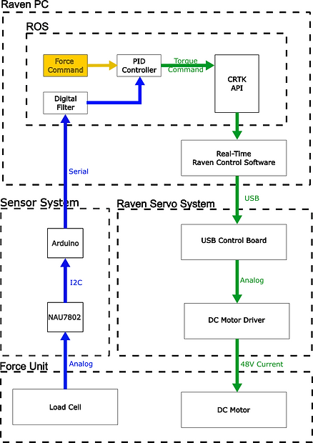
In our contact force estimation project, we modified the Raven's control software to access motor torque control. However, this introduced a significant delay between the feedback signal and the control update.
The Arduino sensor system simultaneously retrieves signals from all six load cells and transmits them to the Raven's PC via serial communication. The signal processing is performed in ROS, where the torque commands are calculated and sent to Raven's real-time thread through the CRTK API. These commands are then transmitted to the servo system via USB and finally converted to analog output by the USB board.


The Delay of Original System
Both the control and feedback signals must pass through multiple platforms, making communication delays unavoidable. Additionally, the Raven-II system requires synchronous motor updates, meaning all six load cells must be read and processed simultaneously. This is particularly disadvantageous for the first load cell, as it must wait for the other five readings to be processed.
Even assuming the operations on the PC are exceptionally fast and the Raven system updates the DAC value immediately after receiving the load cell readings (which is unlikely), there would still be a 5.2 ms delay between the first load cell reading and its control update.
Feedback Pathway With New Motor Control Board
Conversely, the new motor control board bypasses Raven's control software entirely, integrating the feedback loop into a single platform.
Force commands are issued within ROS and transmitted to the motor control board via USB serial interface. The communication overhead at this stage is minimal and does not compromise system stability, as the feedback loop operates directly on the STM32 MCU.
By removing communication overhead, the control system's delay is significantly reduced.


Further Reduce the Delay: Decentralized Controller
With the new motor control board design, we've decoupled the DAC chips, enabling a decentralized control system. The original USB board used SPI to daisy-chain all the DAC chips, requiring simultaneous updates.
The new board connects the DAC chips in parallel, and with the NAU7802 chip's trigger function, the controller can update each motor's control as soon as its feedback signal is ready.
Our prototype's timing diagram shows a consistent 0.7ms delay across all motors, an over 80% reduction from the original system's most optimistic estimate.
The Firmware Structure Overview
The entire control system has 6 threads in total. The synchronization and communication between threads are done through the kernel services provided by Zephyr.


Organization of Motor Control Module
Each motor is controlled by an independent motor control module, which is composed of two parts: MotorStateMachine and MotorTorqueControl threads.
The MotorStateMachine thread receives the external event and changes the behavior of the motor. It is also in charge of initializing the filter buffer, PID controller, and setting up the trigger handler for the load cell when the system is powered on.
The MotorTorqueControl thread is essentially a super loop that does the actual signal processing and PID control and is triggered by NAU7802.
The USB Communication Thread
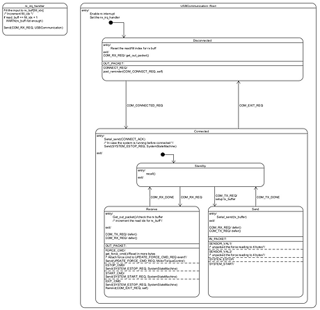
The controller communicates with the host PC through USB. The thread receives control commands from the host PC and sends the system information back to the host PC. The communication interface is modeled in a hierarchical state machine to handle different connection stages and transfer/receive requests.
